Types of Earthing, with Plate and Pipe Earthing Diagrams
The types of earthing used in Indian buildings are plate, pipe, rod, strip and chemical (maintenance-free) earthing. Each buries a metal electrode in the soil and joins it, by an earth wire, to the earth pin of every 3 pin socket. Below we draw a plate earthing pit and a pipe earthing pit, give the electrode sizes commonly taught from IS 3043, and show how an electrician checks earthing with a multimeter and an earth tester.
Key takeaways
- Earthing — a low-resistance path to the ground, so a fault can trip the MCB or RCCB and metal bodies stay safe to touch.
- Plate, pipe, rod, strip, chemical — five ways to make the electrode; plate and pipe are the textbook pair.
- IS 3043 sizes as taught — plate 60 × 60 cm; GI pipe 38 mm bore and 2.5 m long; rod 12.5 mm copper or 16 mm GI.
- Checking — a multimeter shows the earth is connected; only an earth tester shows how good it is.
- ⚠ We make the socket end (3 pin sockets, plug tops, MCBs), not electrodes, compound or testers.
Types of earthing: the short answer
Earthing connects the metal parts of an electrical installation to the ground, so a fault sends current into the soil instead of through a person. The types of earthing differ only in the electrode buried in the ground: a plate, a pipe, a rod, a strip or wire, or an electrode packed in a chemical compound.
ITI and diploma courses teach plate and pipe earthing in most detail, with the electrode sizes taken from IS 3043, the Indian code of practice for earthing. Rod and chemical (maintenance-free) earthing are increasingly what you will see on new sites, and strip earthing appears where rock makes a deep pit hard to dig.
We are the other end of the earth wire. Every 3 pin socket and 3 pin plug top we make in Mumbai carries an earth pin, and our MCBs and MCB boxes sit in the board the earth bar is fixed to. We do not make earth electrodes, chemical earthing compound or earth testers, and we say so rather than imply otherwise. Earthing a building is a licensed electrician’s job.
What is earthing and why is it needed?
Earthing means connecting the exposed metal parts of an installation to the general mass of the earth through a low-resistance path, so that if a phase wire touches a metal body, the fault current flows to earth, the MCB, fuse or RCCB disconnects the supply, and the metal does not stay at a dangerous voltage.
Without earth, a phase wire touching the metal body of an iron or a washing machine leaves that body live, and the first person to touch it becomes the path to ground. With a good earth, the fault current path is the earth wire, the fault current trips the MCB if the earth path is low enough in resistance, and the body stays safe to touch. Where the earth resistance is too high for that, an RCCB is what cuts the supply quickly.
Two words get mixed up (our phase, neutral and earth guide sets them side by side). The neutral carries the normal return current of every load. The earth carries current only when something has gone wrong. An RCCB relies on that difference: it trips when current leaks to earth. An MCB alone does not protect against shock; see which MCB for home.
In Hindi the word on site is simply अर्थिंग (earthing); Hindi science textbooks call the earth wire भूसंपर्क तार (bhoosampark taar, “ground-contact wire”).
Never use the neutral as an earth, and never join earth to neutral at a socket. Both hide a fault until someone touches a metal appliance.
| Type | Electrode | Size commonly taught | Upkeep | Where used |
|---|---|---|---|---|
| Plate | Copper or GI plate, set upright | 60 × 60 cm; copper 3.15 mm or GI 6.3 mm thick; top at least 1.5 m deep | Watering in dry months; periodic tests | Buildings; the classic textbook method |
| Pipe | GI pipe with holes along it | At least 38 mm bore and 2.5 m long | Water through its funnel; periodic tests | Homes and buildings; common ITI practical |
| Rod | Copper, steel or GI rod driven in | Copper 12.5 mm or steel/GI 16 mm diameter; at least 2.5 m long | Low | Tight plots, paved areas; often several rods |
| Strip or wire | GI or copper strip laid in a trench | Set by the design | Low | Rocky ground; joining electrodes |
| Chemical (maintenance-free) | Rod or pipe in conductive compound | Set by the compound maker | Little or no watering; still tested | Newer homes, offices, equipment rooms |
What is plate earthing and what size is the plate?
Plate earthing buries a copper or galvanised iron plate upright in a pit, with its top at least 1.5 m below ground, surrounded by layers of charcoal and salt, and joins it to the installation by an earth lead, with a watering pipe and funnel bringing water down to keep the soil around it moist.
Plate earthing diagram: the pit in section
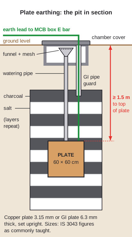
Drawn by us, not to scale. Sizes are the IS 3043 figures as commonly taught in ITI. Tap the diagram to open it full size.
The plate earthing size commonly taught from IS 3043 is at least 60 cm × 60 cm, either copper, 3.15 mm thick or GI, 6.3 mm thick, with its top at least 1.5 m deep. The installation designer works to the current edition of the code, so treat these as the textbook values.
The earth lead is bolted to the plate and brought up inside a GI pipe guard so it cannot be cut by a spade later.
An earth pit is dug only after buried water pipes, gas lines and cables have been located. A spade through a buried cable is its own shock hazard.
60 × 60 cm plate, upright, top at least 1.5 m deep.
GI pipe, 38 mm bore, 2.5 m long, watered through a funnel.
Driven rod, no big pit; add rods if one is not enough.
Electrode in compound; less watering, still tested.
What are the layers of an earthing pit?
An earthing pit, in the traditional plate or pipe method taught in ITI, has the electrode at the bottom, alternate layers of charcoal and salt packed around it, backfilled soil above, and at the top a small masonry chamber with a cover that holds the watering funnel and the joint of the earth lead.
Each layer has a job. The electrode is the metal that meets the soil. Charcoal holds moisture around it. Salt makes the moist soil conduct better. The chamber and cover keep the top open for inspection, watering and testing, and the funnel with mesh lets water in without letting soil fall down the pipe.
The weakness of the method is chemistry: salt corrodes metal, so a GI electrode in salt is slowly eaten away, and the earth resistance creeps up in a dry season when the pit dries out. That is why old pits are watered and tested, and why chemical earthing exists.
Layer thickness and backfill differ between textbooks and between sites. Follow your instructor in the workshop, and the installation’s design on a real job.
What is pipe earthing? Diagram and size
Pipe earthing uses a galvanised iron pipe, commonly taught from IS 3043 as at least 38 mm internal diameter and 2.5 m long, with holes along its length, set upright in the soil with charcoal and salt around it and a funnel at the top, so water poured in reaches the soil through the holes.
Pipe earthing diagram: the pit in section
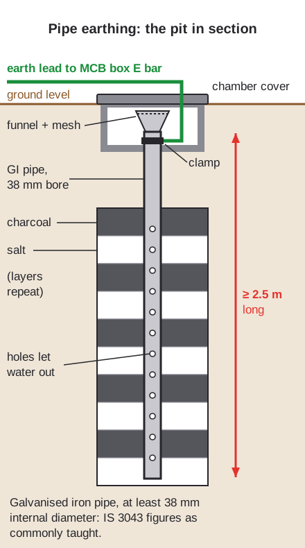
Drawn by us, not to scale. Sizes are the IS 3043 figures as commonly taught in ITI. Tap the diagram to open it full size.
The figures to remember: 38 mm bore and 2.5 m long at least, in GI. The earth lead is clamped near the top of the pipe inside the chamber, where it can be inspected and re-tightened.
The funnel sits on the pipe itself, so watering is easy: pour water in and the holes spread it into the soil around the full length.
Pipe earthing is the one most ITI practicals build, because a GI pipe is easy to get, drill and water.
Plate earthing and pipe earthing: which is better?
Neither plate nor pipe earthing is better everywhere: textbooks present pipe earthing as the cheaper, more common method for buildings, because a GI pipe costs less than a copper plate and is easy to water, and plate earthing as the method with the larger flat contact area, chosen where the design calls for it.
Side by side: pipe uses less metal, is easy to water through its own funnel and goes in a narrower pit. Plate offers a large contact area but needs a big, deep pit, and a copper plate is costly.
In both, the value that matters is the earth resistance measured after installation, not the method on paper. Soil decides a lot: dry, sandy or rocky ground gives a higher reading than moist clay, which is why one electrode may not be enough and a second is added.
Rod and chemical earthing, below, are what many new sites now use instead of either.
The method is chosen by the electrician or designer for the soil and the installation. A student should know the sizes and the reasons, not pick one by habit.
What is rod earthing and strip earthing?
Rod earthing drives a copper rod of at least 12.5 mm diameter, or a steel or GI rod of at least 16 mm, at least 2.5 m into the ground, as commonly taught from IS 3043, while strip earthing lays a GI or copper strip horizontally in a trench where rock makes deep digging hard.
The rod figures: copper 12.5 mm or steel/GI 16 mm diameter, 2.5 m long at least. A rod needs no big pit: it is driven in, so it suits paved compounds and tight plots. Where one rod does not give a low enough reading, several rods are driven well apart and joined.
Strip earthing runs the electrode sideways instead of down. It suits rocky ground and is also used to join several electrodes into one system.
Wire earthing in textbooks is the same idea as strip earthing, with bare copper or GI wire laid in the trench. Do not confuse it with the earth continuity conductor, the green or green-yellow earth wire that runs with every circuit from the MCB box to each socket: not an electrode, but half the system.
Never drive a rod or dig a trench where cables or pipes may be buried. Locate services first.
Chemical earthing kaise karen? What maintenance-free earthing is
Chemical earthing, sold as maintenance-free earthing, places a metal electrode, usually a copper-bonded or GI rod or pipe, in a bored hole and fills the space around it with a conductive backfill compound instead of charcoal and salt, so the soil around the electrode stays conductive with little or no watering.
“Chemical earthing kaise karen” asks how it is installed. In outline: bore the hole, set the electrode, fill with compound mixed as its maker specifies, backfill, fit the inspection chamber, connect the earth lead, then test the resistance.
The appeal is steady resistance through dry months and less corrosion than salt. The quantities, hole size and mixing are set by the compound’s maker, so follow their sheet rather than a rule of thumb.
We do not make chemical earthing electrodes or compound. What we make sits at the other end: the earthed sockets and plug tops covered below.
“Maintenance-free” does not mean test-free. A chemical earth is still tested with an earth tester after installation and at intervals afterwards.
Earthing kaise check kare multimeter se?
To check earthing with a multimeter, an electrician sets it to AC volts and measures at a socket, first phase to neutral, then phase to earth, then neutral to earth: on a properly earthed point the phase–earth reading is close to the phase–neutral reading, and neutral to earth reads close to zero.
The pattern a healthy earthed socket shows on a multimeter
An illustrative pattern, not measured values; bar lengths only rank the readings. 230 V is India’s nominal single-phase supply.
A low phase–earth reading means the earth path is missing or poor. A high neutral–earth reading points to a neutral or earth fault worth tracing.
A multimeter shows the earth is connected, not how good it is. A neon line tester such as our VIYONA line tester 811 (code 198, ₹36 MRP) shows only that phase is present; it says nothing about earth, and no glow does not prove a circuit dead.
This is a live test. It is done by a trained electrician with a meter and probes rated for mains, fingers behind the probe guards. Students do it only under an instructor.
How is earth resistance measured with an earth tester?
Earth resistance is measured with an earth tester using the fall-of-potential method taught in ITI: the electrode is disconnected from the installation, two test spikes are driven into the soil in a line away from it, the tester passes current through the far spike, reads the voltage at the middle one, and shows the resistance in ohms.
The tester’s terminals are usually marked E for the electrode, P for the potential spike and C for the current spike. The textbook rule is to set P at about 62% of the distance from the electrode to C, then move it a little either way: a steady reading means the spikes are far enough out.
Lower is better. The value an installation needs depends on what it is and on the design, so the electrician compares the reading with that. Test in the dry season for the worst case, and record the date and reading at the chamber.
We do not make earth testers. The instrument is an electrician’s tool, and the test is part of commissioning an installation.
Never disconnect the earth lead of an installation that is switched on. Isolate the supply first, test, then reconnect before switching back on.
What is the earthing symbol, and which pin is earth?
The earthing symbol is a vertical line ending in three horizontal lines that get shorter towards the bottom, and the protective earth symbol puts that sign inside a circle; the earth wire in an Indian installation is green or green-yellow, and it ends at the larger, longer third pin of every 3 pin plug and socket.
The other symbols on a wiring plan are drawn in our electrical symbols guide.
The earth pin is longer so it connects first and breaks last, and thicker so it cannot enter a live hole; our 3 pin plug guide explains both. Our Royal 3 pin plug top is 243 6A ₹68 and 244 16A ₹110; the Deluxe is 241 at ₹64 and 242 at ₹105, all MRP.
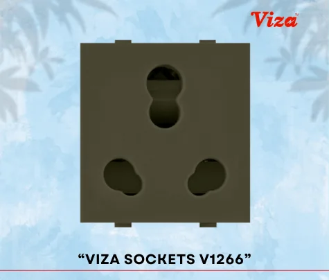
The sockets they plug into all carry the earth contact: VIYONA 119 3 pin socket ₹40, KEMPS K192 6A ₹110, KEMPS K193 6A & 16AX universal ₹205 and VIZA V1266 16A ₹179. See 6A vs 16A socket to choose.
Never cut, bend or break off an earth pin to fit a 2 pin socket. Have a 3 pin point installed instead.
Earthing kaise kare? How a house is earthed, step by step
A house is earthed by a licensed electrician who makes the earth electrode outside, runs an earth lead to the earth bar in the MCB box, connects the green earth wire of every circuit to that bar, takes each one to every socket’s earth terminal, and tests earth resistance and continuity before the supply is switched on.
- Choose the electrode for the soil: plate, pipe, rod or chemical.
- Make the pit or drive the electrode, with its chamber.
- Run the earth lead, protected, to the MCB box earth bar.
- Draw an earth wire with every circuit to each 3 pin socket and metal fitting.
- Test earth resistance and continuity; record the readings.
The board end is where we come in: VIYONA 401 single pole ₹145 and 411 double pole ₹350 10 kA MCBs, made to IS/IEC 60898-1, and the 371 2–4 way SPN MCB box at ₹380 MRP. We make no RCCB; your electrician specifies one.
The L, N and E terminals at each socket are drawn in our switch board wiring diagram.
MCB off and test dead before any work at a board. Earthing work on a live installation is for a licensed electrician only.
FAQs
What are the types of earthing?
Earthing kaise kare?
Earthing kaise check kare multimeter se?
Chemical earthing kaise karen?
What is the plate earthing size?
What is the earthing symbol?
Why buyers choose Vinayak Electricals
- Every 3 pin socket and 3 pin plug top we make carries the earth pin or earth contact.
- VIYONA, KEMPS and VIZA 3 pin sockets in 6A and 16A, made in-house at our works in Mumbai.
- VIYONA Royal, Deluxe and Decent 3 pin plug tops in 6A and 16A, with MRPs in our catalogue.
- VIYONA MCBs made to IS/IEC 60898-1, licence CM/L-2544151, for the board the earth bar sits in.
- VIYONA SPN MCB boxes from 2 to 18 way, and double door distribution boards.
- Manufacturing in Mumbai since 1995.
Earthed plugs and sockets
See our 3 pin plug tops and the sockets they fit, with codes and MRPs.
View 3 pin plugs