A Switch Board Wiring Diagram You Can Actually Follow
A switch board wiring diagram is simpler than it looks: the phase from the MCB goes to every switch, each switch sends a switched phase to its own light, fan or socket, and the neutral and earth go straight to the loads. Below, we draw it step by step, from one switch and one light to a full 8-module bedroom board. Along the way we cover the indicator, fan regulator and 3 pin socket, with the codes and MRPs of the parts we make in Mumbai.
Key takeaways
- Phase to the switch — every switch breaks the phase, never the neutral.
- Parallel board, series switch — loads sit side by side; each switch is in series with its own load only.
- Indicator — across the switched phase and neutral, so it needs a neutral at the board.
- Fan regulator — MCB, fan switch, regulator, fan, in that order on the phase.
- ⚠ MCB off, test dead before any wire is touched; the wiring itself is a job for a licensed electrician.
Switch board wiring diagram: the short answer
A switch board wiring diagram shows three things: the phase wire from the MCB looping to every switch, a switched phase leaving each switch for its own light or fan, and the neutral and earth going straight to the loads and sockets without passing through any switch.
The four diagrams below cover one switch and one light, an indicator, a fan regulator and a full 8-module bedroom board. Each one names every wire in words.
We make switches, sockets, regulators, plates and MCBs at our works in Marol, Andheri East, Mumbai, so the codes and MRPs below are from our catalogue. We cannot see your wiring: if anything behind your plate differs from these diagrams, stop and call a licensed electrician.
How do you wire a switch board?
You wire a switch board by bringing the phase from the MCB to one terminal of each switch, running a switched phase from each switch’s other terminal to its light or fan, taking the neutral directly to every load and socket, and connecting the earth to each socket’s earth pin, all with the MCB switched off.
Basic switch board wiring diagram: one switch, one light
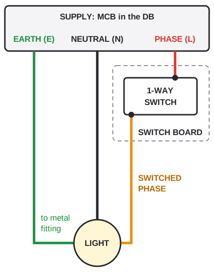
Drawn by us. The switch breaks the phase; the neutral and earth never pass through it. Wire colours vary between older and newer installations, so confirm every wire with a tester. Tap the diagram to open it full size.
Four wires do all the work. The phase (L) arrives from the MCB and is looped from switch to switch with short jumpers. Each switch sends out a switched phase to its own load. The neutral (N) goes to the light, fan or socket directly, and the earth (E) goes to every socket and metal fitting.
A 1-way switch has two terminals, so on a basic point either can take the phase.
Switch off the MCB that feeds the board and prove it dead with a tester before the plate comes off. If you cannot tell which MCB feeds the board, call a licensed electrician.
| Module | Wire in | Wire out | Our example |
|---|---|---|---|
| 1-way switch | Phase | Switched phase to the load | KEMPS K101 (₹65) |
| 2-way switch | First switch: phase on COM. Second switch: two travellers on L1 and L2 | First switch: two travellers from L1 and L2. Second switch: switched phase from COM to the light | KEMPS K102 (₹105) / VIZA V1202 (₹90) |
| Switch with indicator | Phase | Switched phase to the load; the lamp also takes a neutral | VIZA V1204 (₹95) / KEMPS K108 (₹120) |
| Fan regulator | Switched phase from the fan switch | Speed-set phase to the fan | KEMPS K213 (₹405) / VIZA V1276 (₹374) |
| 3 pin socket | Switched phase, neutral and earth | None | KEMPS K192 6A (₹110) / VIZA V1266 16A (₹179) |
| Indicator module | Switched phase and neutral | None | KEMPS K217 (₹95) / VIZA V1251 (₹83) |
Which wire goes to the switch, phase or neutral?
The phase wire goes to the switch, never the neutral, because a switch in the phase cuts the live supply to the light or fan when it is off, while a switch in the neutral leaves the holder, the fan terminals and the wiring beyond the switch live even with the switch off.
That is the single most important rule on any board: switch in the phase, never a switch in the neutral. A light wired the wrong way still works, so the mistake survives until someone changing a bulb touches a live holder.
On site, colour is only a first clue. In many older homes red = phase and black = neutral; in some newer installations brown = phase and blue = neutral; earth is green or green-yellow.
A line tester glows on the phase, so it shows which wire is live; our VIYONA line tester starts at ₹36 MRP. No glow is not proof that a circuit is dead: confirm that with a voltage tester, or ask an electrician.
Never trust wire colour alone. Test each wire, and label the phase with a strip of tape before you disconnect anything.
The phase loops to one terminal of every switch on the board.
The neutral goes straight to each light, fan, socket and indicator.
The earth goes to every socket’s E terminal and metal fitting.
Fan switch first, then regulator, then fan, all on the phase.
How is a switch board connected, series or parallel?
A switch board is connected in parallel, because every switch takes its own feed from the same phase and every light, fan and socket sits across phase and neutral on its own path, while each switch is in series with only its own load, so one load switched off does not turn off the others.
Both words are true. Between loads the board is parallel: the light, the fan and the socket each see the full supply voltage. Between a switch and its load the connection is series: the switch sits in the path of that one load’s phase and nothing else’s.
Because every switch input shares the phase loop, pressing S1 for the light leaves S2 for the fan untouched.
What sits in series and what in parallel on a board
Series A switch and its own load. A fan switch, its regulator and the fan.
Parallel The light, the fan and the socket, each across phase and neutral. An indicator and the load it shows.
Series means one path: open the switch and that load stops. Parallel means separate paths: switching one load off leaves the others running.
If two lights glow dim together and both go out when one bulb fails, they have been wired in series by mistake. Switch off and have the board rewired.
How do you connect an indicator in a switch board?
An indicator in a switch board is connected across the switched phase and the neutral, so it glows only when its switch is on; it needs its own neutral wire at the board, which is why an indicator switch typically has one more terminal than a plain switch and why a board without a neutral cannot light one.
Switch board connection with indicator
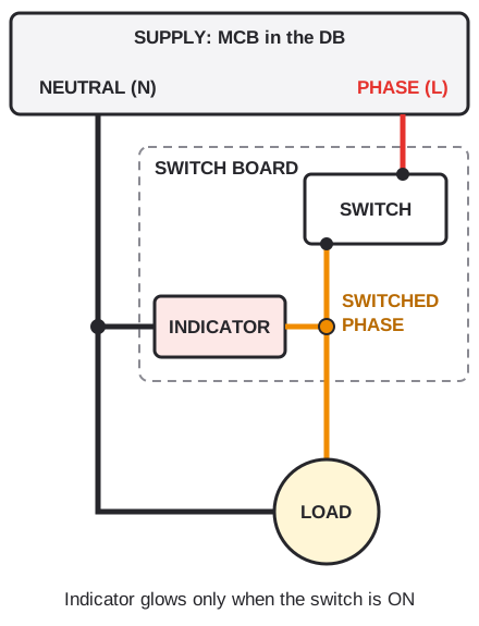
Drawn by us. The indicator taps the switched phase and returns on the neutral. Follow the terminal marks on your module. Wire colours vary between older and newer installations, so confirm every wire with a tester. Tap the diagram to open it full size.
There are two ways to add one. A switch with indicator has the lamp built in: VIZA V1204 is a 10 A 1-way switch with indicator and an MRP of ₹95, and the KEMPS K108 is a 20AX 1-way switch with indicator at ₹120 in white. A separate indicator module sits beside the switch: the KEMPS K217 6A red indicator is ₹95 and the VIZA V1251 6A neon indicator ₹83.
Indicators earn their place on geyser, motor and heater points, where you want to see that something is running.
No neutral at the board? Many older boards have none, and running one is an electrician’s job.
How do you connect a fan regulator in a switch board?
A fan regulator is connected in series with the fan on the phase side: phase from the MCB goes to the fan switch, the switched phase goes from the fan switch to the regulator, and the regulator’s output goes to the fan, while the neutral runs straight to the fan without touching the regulator.
Switch board connection with fan regulator
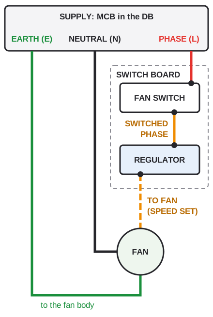
Drawn by us. Order along the phase: MCB, fan switch, regulator, fan. Wire colours vary between older and newer installations, so confirm every wire with a tester. Tap the diagram to open it full size.
The switch turns the fan on and off; the regulator sets its speed. KEMPS K213 is a 4 step electronic fan regulator with an MRP of ₹405 in white, and the K214 5 step is ₹450. In VIZA Black, the V1276 4 step is ₹374 and the V1277 5 step ₹433. Pick the step count with our fan regulator types guide: 5 step for a bedroom’s slow night speed, 4 step for most other rooms.
A regulator takes 2M on a KEMPS board, so count it when you choose the plate.
Never fit a light dimmer in place of a fan regulator. A dimmer is built for lamps; on a fan motor it can hum, overheat and fail.
The phase leaves the board through the switch and regulator; at the fan itself, the fan capacitor connection splits it between the run and start windings.
How is a 3 pin socket connected in a switch board?
A 3 pin socket in a switch board takes three wires: the switched phase from its own switch to the L terminal, the neutral to the N terminal, and the earth to the E terminal behind the larger pin, with the switch breaking the phase so the socket is dead when the switch is off.
The three terminals are marked L, N and E on the back of the module. The earth gives a fault current a safe path away from anything a person can touch.
Wires at each module, in common practice
Typical counts in common practice; bar length follows the count. A different number means stop and check.
Match the switch to the socket. A 6A socket such as the KEMPS K192 6A 3 pin socket with shutter (₹110) suits a 10AX switch. A 16A socket such as the VIZA V1266 16 A porcelain socket (₹179) needs a switch rated at least 16A, so use a 20A one, on a circuit wired for 16A. See 6A vs 16A socket.
Never join earth to neutral at a socket, and never leave the earth terminal empty. Both hide a fault until someone touches a metal appliance.
A typical bedroom switch board, wired end to end
A whole bedroom board: a light switch, a fan switch and regulator, and a switched 6A socket on one 8-module plate. It is the basic diagram repeated three times off one phase loop.
8-module bedroom switch board wiring diagram
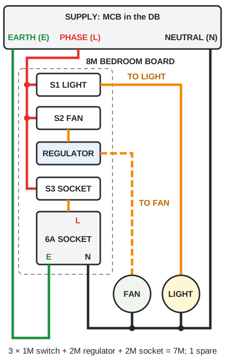
Drawn by us. One phase loop feeds S1, S2 and S3. Wire colours vary between older and newer installations, so confirm every wire with a tester. Tap the diagram to open it full size.
In KEMPS, at printed MRP in white: three Orchid K141 10AX 1-way switches at ₹65 each, a K213 regulator at ₹405, a K192 6A socket at ₹110 and an Orchid 8M plate K306 at ₹290, for ₹1,000 in total.
8M KEMPS bedroom board at MRP (₹1,000 total)
Catalogue MRPs (white), bars to scale against ₹405. The spare module can take a K217 indicator (₹95).
The module sum is 7M, so the 8M plate leaves one spare. Modular plate sizes explained shows how to count a board.
What wire size is used in switch board wiring?
Switch board wiring in Indian homes commonly uses 1.5 sq mm copper wire for lights and fans and 2.5 sq mm for socket circuits, as common practice, with heavier sizes for geysers, ACs and the main line, but the size of each run is set by your electrician for its load, length and how it is laid.
1.5 sq mm is the size you will most often find on light and fan circuits, and 2.5 sq mm on 6A and 16A socket circuits. Our house wire guide covers sizes, coil lengths and MRPs for our VIYONA wire.
The short phase loop jumpers between switches carry the current of every load on the board together, so they should be the same size as the incoming phase, never a thinner offcut.
The MCB rating must suit the cable, not the other way round.
A thin offcut used as a phase loop can overheat as loads are added. Every jumper should match the incoming phase wire.
How does a 2-way switch connect on a switch board?
A 2-way switch on a switch board has three terminals: at the first switch the phase goes to the common terminal, two traveller wires run from its L1 and L2 to L1 and L2 of a second 2-way switch elsewhere, and that switch’s common terminal sends the switched phase on to the light.
On the board, a 2-way switch takes the same 1M space as a 1-way, so it does not change the plate size. VIZA V1202 is a 10 A 2-way switch with an MRP of ₹90, and the KEMPS K102 10AX 2-way is ₹105 in white.
The common terminal is the one that matters. Mark it with tape before disconnecting an old 2-way switch, because a common on L1 is the usual reason a staircase light works from only one end. Our 2-way switch wiring diagram draws the full pair, and 1 way vs 2 way switch explains the difference.
A 2-way switch also works as a 1-way: phase to common, load to L1 or L2, third terminal empty.
One traveller is always live, whichever way the first switch points, even when the light is off. Switch off the MCB and prove both boards dead before opening either one.
Tools and safety before you wire a switch board
An electrician’s kit for a board is a voltage tester, an insulated screwdriver that fits the terminal screws, a wire stripper, insulation tape and a torch. The tester matters most.
The routine never changes. MCB off, then test dead at the board, then work. Check the tester on a known live point first.
Strip just enough insulation, with no bare copper showing and no stray strands. Tighten firmly and tug each wire; a loose terminal is a common cause of a switch heating up later. Replace a switch in a switch board walks through a single module.
Some jobs are an electrician’s from the start: a DP switch for a geyser or AC, any change of rating, aluminium wires, or burn marks behind the plate.
No live work, ever. If you are unsure at any point, stop, leave the MCB off and call a licensed electrician.
Switch board wiring kaise karen: the steps in order
If you searched “switch board wiring kaise karen”, this is the order an electrician follows:
- Switch off the MCB and prove the board dead with a tester.
- Identify and label the incoming phase, neutral and earth.
- Loop the phase to one terminal of every switch.
- Run each switch’s other terminal to its light, fan regulator or socket L.
- Take the neutral to each load, socket N and indicator.
- Take the earth to every socket E and metal fitting.
- Fit the modules, close the plate, switch on and test.
Step 3 is where boards go wrong: a missed loop leaves one switch dead, and a loose loop heats the whole row. Step 7 means testing every switch and every socket, not just the first.
Looking for a switch board wiring diagram PDF? Every diagram on this page is a standalone image: print the page or save as PDF from your browser and keep it with the board plan.
Photograph the back of each board before it is closed, so the next electrician knows which wire went where.
Common switch board wiring mistakes
A switch in the neutral leaves the light holder live when it is off. A missing earth at a 3 pin socket leaves a metal appliance with no fault path. A dimmer on a fan hums and overheats. And a 16A socket on a 6A switch makes the switch the weak point.
Thin phase loops warm up as more loads are added. Two wires under one screw work loose. A 2-way common on the wrong terminal makes a staircase light work from only one end.
If a switch or socket is warm to touch, smells of burning or shows brown marks on the plate, switch off the MCB and read our guide to a switch getting hot or socket sparking. For choosing the modules in the first place, see how to choose a switch board.
Our switches carry the IS 3854 licence and our sockets IS 1293; correct wiring is what lets those ratings do their job.
A warm plate is a warning, not a quirk. Switch off and have the board checked before the next use.
FAQs
How do you wire a switch board?
Is a switch board connected in series or parallel?
Which wire goes to the switch, phase or neutral?
How do you connect an indicator in a switch board?
How do you connect a fan regulator in a switch board?
Is there a switch board wiring diagram PDF?
Why buyers choose Vinayak Electricals
- Switches, sockets, fan regulators and indicators made in-house at our works in Marol, Andheri East, Mumbai.
- Switches made under IS 3854 (ISI CM/L-7567794) and sockets under IS 1293.
- 1-way, 2-way and indicator switches, 6A and 16A sockets and 4 and 5 step regulators in KEMPS and VIZA, so one board can come from one range.
- MCBs and MCB boxes in our VIYONA range for the circuit that feeds the board.
- MRPs published in our catalogue; sold through 500+ dealers across India, in full boxes.
- Manufacturing in Mumbai since 1995; ISO 9001:2015 certified.
Switches, sockets and regulators for every board
See the KEMPS range of switches, sockets and regulators, with codes and MRPs.
View KEMPS switches